
Decoding Thermostat Wiring: A Step-by-Step Guide
Learn advanced wiring techniques for multi-stage, heat pump, and variable-speed HVAC systems. Follow a systematic approach to safely connect and test thermostat circuits.
HVAC
3/21/20256 min read
What This Post Covers
Essential terminology and color coding for advanced HVAC thermostat setups
Step-by-step wiring strategies for multi-stage heating/cooling and heat pump systems
Sequence-of-operation insights to verify proper connections
Practical tips for testing and troubleshooting unusual or proprietary wiring schemes
“Easy way out” methods for isolating common faults
Support options from SuperTech Industries for complex setups
Taking Thermostat Wiring to the Next Level
Traditional single-stage systems might have taught you the basics of matching R, G, Y, W, and C wires, but modern HVAC setups are far more dynamic. Multi-stage furnaces, heat pump reversing valves, dual-fuel hybrids, and variable-speed air handlers each add complexity to the wiring puzzle. Understanding these advanced wiring principles not only avoids short circuits or misconfiguration—it also ensures top efficiency and precise comfort control.
Many advanced thermostats, especially “smart” ones, require specialized connections. They rely on the C-wire (common) to draw steady 24V power, or have dedicated terminals for second-stage cooling/heating calls. Some heat pumps demand an O/B wire for reversing valve actuation, while multi-stage systems might use Y1/Y2 and W1/W2 lines for multi-level heating and cooling. Learning to decode these intricacies allows you to upgrade or replace thermostats with confidence, eliminating guesswork and repeated rewiring attempts.
Key Wire Labels and Functions
Understanding standard color codes is a solid starting point, though real systems can deviate:
R (Red): 24V power from the HVAC transformer.
RC/RH: Separate 24V circuits for cooling and heating when they come from different transformers, or they may be bridged if only one transformer exists.
G (Green): Blower or fan relay control.
Y1, Y2 (Yellow): First and second stages of cooling. Y1 typically calls for the main AC or heat pump compressor; Y2 energizes additional capacity if available.
W1, W2 (White): First and second stages of heat. W1 triggers the primary heating source (furnace, heat strips), W2 handles auxiliary or secondary heating.
O/B (Orange/Blue): Reversing valve for a heat pump. “O” is often used for systems that energize the valve in cooling mode, while “B” might energize in heating mode.
C (Blue or Black): The 24V common or return path, crucial for powering advanced or smart thermostats.
Tip: If you see a wire color used for an unusual purpose—like a brown wire substituting for W2—don’t rely solely on color. Cross-check the furnace or air handler’s control board to confirm each wire’s actual function.
Laying Out a Systematic Wiring Process
1. Identify Equipment Type and Stages
Before touching any wires, confirm the HVAC system’s capabilities:
Single-stage vs. two-stage heating or cooling
Conventional AC + furnace vs. heat pump with reversing valve
Additional accessories (humidifiers, dehumidification controls, etc.)
This clarifies which thermostat terminals you’ll need to utilize. If you’re working with a dual-fuel or hybrid system (heat pump plus furnace), expect more wires for controlling both gas heat and the heat pump’s reversing valve or auxiliary heat.
2. Turn Off Power and Label Everything
Even advanced HVAC pros risk short circuits if they rush. Always cut power at the breaker/fuse box to the air handler or furnace and the condensing unit. Use small tags or tape on each wire before disconnecting them—especially if the previous thermostat or harness had no labeling. This precaution is lifesaving if you get called away mid-project and need to remember each wire’s function later.
3. Match Wires to Thermostat Terminals
A typical multi-stage heat pump scenario might involve:
R to R (or RC/RH, depending on jumpers)
O/B for the reversing valve (energized in cool or heat mode, depending on system config)
Y1 for stage one compressor, Y2 for stage two (if available)
G to control the indoor fan relay
W2 (or AUX) for backup/emergency heat
C for common 24V return
Each brand can vary. Some advanced thermostats have “O/B” combined into one terminal with a software toggle that sets whether the valve is energized in cooling (O) or heating (B).
4. Confirm DIP Switches or Jumper Settings
Many thermostats or control boards incorporate small DIP switches, jumpers, or programming selections to define how the system handles reversing valves, second-stage timing, or fan control. Read the manual carefully: a reversing valve can be energized only in cooling or only in heating, and getting this backward means the heat pump runs in the wrong mode.
5. Tidy Connections and Shield Wires
Stranded thermostat wires can easily short if any stray copper strands touch an adjacent terminal. Inspect each connection, ensuring you snugly tighten the screw and no bare copper extends beyond the clamp. If you have leftover wires (like blue or brown not used), curl or tape them out of the way to prevent accidental contact.
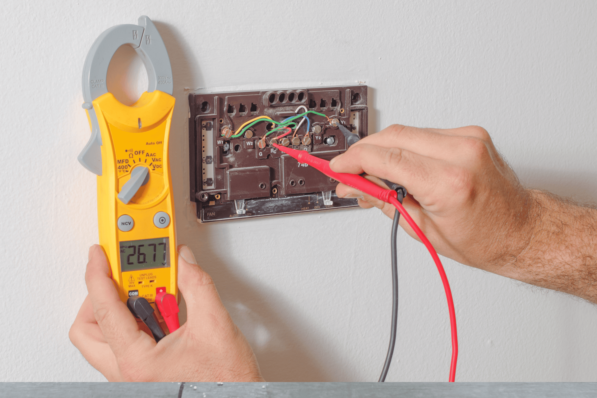
Verifying Proper Operation through Sequence of Operation
Once wired, check the sequence of operation to confirm each stage or function engages as intended:
Fan Call (R to G): The indoor blower should energize alone, no compressor or heat triggers.
Cooling Stage: Combine R with Y1, see if the outdoor unit and blower power up. If there’s a second cooling stage, add Y2 to ensure the system transitions smoothly without lockouts.
Heating Stage: Pair R with W1 for stage one heat. For multi-stage, add W2 calls if you have dual-stage heat or an auxiliary scenario.
Reversing Valve: On a heat pump, engage the O/B line in the correct mode (cooling or heating). Listen for the valve clicking. Confirm the system is blowing hot air in heat mode, cold air in cool mode.
Tip: If the system reacts unpredictably, reevaluate each circuit. For instance, hooking an O wire to the B terminal inadvertently inverts the reversing valve logic, reversing heat and cool modes.
“Easy Way Out” Test for Low-Voltage Shorts
Complex thermostat wiring can sometimes mask a short circuit. A high-level trick is to energize one circuit at a time:
Fan Only: Connect R to G. If the blower runs and no fuse blows, the G circuit is likely good.
Cool Only: Reconnect R to Y1 (and possibly O/B for heat pumps). Check if the outdoor unit runs.
Heat: R to W. If the furnace lights up without shorting, the heat wiring is fine.
By isolating each path, you can pinpoint where the short actually resides instead of pulling the entire thermostat off in frustration.
Addressing Proprietary or Smart Thermostats
Some advanced thermostat models don’t strictly follow the color-coded terminals of older systems, especially if they communicate via data lines or incorporate brand-specific connectors. In these cases:
Review Brand Manuals: High-end equipment from certain manufacturers might run multiple zones from a single digital thermostat that requires proprietary wiring harnesses.
Check Extra Modules: Some smart thermostats use “power extenders” to create a C-wire where none exists, or they integrate with custom boards. Make sure you secure the module near the HVAC control board, verifying the 24V signals pass correctly.
If a thermostat claims “no C-wire needed,” it might rely on power-stealing from the R-W or R-Y circuit, causing potential flickers or system malfunctions if the control board isn’t designed for that usage. In such scenarios, fully read the installation notes to avoid partial compatibility issues.
Common Pitfalls to Avoid
Mislabeling O and B: In typical heat pump systems, “O” energizes the reversing valve in cooling mode, while “B” does so in heating mode. Mixing them up flips your system’s hot/cold functions.
Forgetting the Jumper between RC and RH: If your heating and cooling share one transformer, keep the factory-installed jumper in place. Removing it might cause half the system to lose power calls.
Unaccounted Second Stages: If the HVAC can handle two stages of cooling or heating but the thermostat never calls for stage two (Y2, W2), you lose performance and risk short or incomplete cycles.
Ignoring Manufacturer Diagrams: Every brand may use slight variations in labeling or DIP switch settings. A quick glance at the furnace or air handler schematic keeps you from guesswork.
Example Scenario: Multi-Stage Heat Pump with Auxiliary Heat
Imagine installing a new programmable thermostat on a two-stage heat pump that also has electric emergency heat. Your connections might look like this:
R or RC tied to the 24V supply.
O (or O/B) designated for the reversing valve, set to energize in cooling.
Y1 for the primary compressor stage, Y2 for the secondary stage.
G controlling the blower fan.
W2 or AUX hooking up electric strips or backup heat.
C providing a common line for thermostat power.
After wiring, you’d program the thermostat to confirm “O is energized in cooling,” allow stage two calls after a certain temperature differential or time delay, and set an option for emergency heat to run if the heat pump cannot handle extreme cold alone.
When to Seek Expert Assistance
Most advanced wiring jobs are doable if you carefully read diagrams and proceed step by step. Still, some scenarios warrant professional support:
You discover dangerously spliced or mislabeled wires in cramped or inaccessible areas.
The system involves proprietary communication lines or brand-specific zoning modules you’ve never encountered.
You suspect voltage irregularities that may damage boards or thermostats.
Repeated fuse blowouts or short circuits persist even after verifying the usual suspects.
SuperTech Industries can assist with complex or custom wiring, ensuring each component communicates reliably and safely.
Final Thoughts: Wiring Confidence for Modern HVAC
Becoming adept at advanced thermostat wiring hinges on having a clear blueprint—both literally, in the form of wiring diagrams, and figuratively, by understanding your system’s sequence of operation. Mapping out each wire’s function, verifying DIP switch or jumper settings, and performing step-by-step checks mitigate confusion and potential damage. Adopting these best practices also means harnessing the full capabilities of modern HVAC systems, from multi-stage comfort to optimized energy usage.
If you find yourself stumped by brand-specific logic boards or uncertain about bridging certain terminals, “Don’t just call a tech, call a supertech.” At SuperTech Industries, we’re experienced in everything from basic furnace thermostats to elaborate heat pump and dual-fuel configurations. We deliver “Simple Solutions. Superior Results.” so you can enjoy a properly wired system that runs smoothly and responds accurately to every comfort call.
SuperTech Industries
Your trusted partner for all your solutions.
KNOWLEDGEABLE - AFFORDABLE - ADAPTABLE - DEPENDABLE
© 2024. All rights reserved.
1530 E Williams Field Road
Ste. 201
Gilbert, AZ 85295


ROC 361165
Licensed - Bonded - insured